
Related News
- 00
0000-00
Choosing Heavy-Lift Crane Vessels for Offshore Projects: Capacity and Outreach - 00
0000-00
Choosing a Ship Component Availability Database: Stock Accuracy and Lead Times - 00
0000-00
How Low-Carbon Navigation Systems Optimize Ship Routes to Reduce Fuel Use - 00
0000-00
How Shipbuilding Supply Chain Lead Times Affect Vessel Delivery Schedules - 00
0000-00
Maritime Digitalization: Where Fleet Operators Can Cut Fuel and Compliance Risk

Which Hull Features Reduce Fuel Use in Bulk Carrier Design?
Low fuel consumption bulk carriers design begins well before the main engine is selected. A bulk carrier may carry a relatively simple cargo, but its operating profile is not simple: loaded and ballast drafts differ widely, port calls can be irregular, weather exposure is substantial, and many vessels spend long periods operating below design speed. A hull that looks efficient at one draft and one speed can be disappointing across a real trading year.
For technical evaluation teams, the useful question is not whether a vessel has an “eco hull.” It is whether the hull form reduces total resistance in the conditions the ship will actually encounter, while preserving deadweight, loading flexibility, longitudinal strength, trim tolerance, manoeuvrability, and buildability. The most effective choices usually involve the bow, forebody, stern flow field, appendages, and underwater-surface condition. They also need to be assessed as one hydrodynamic system rather than as a collection of fuel-saving labels.
The starting point: resistance at loaded and ballast condition
A conventional bulk carrier operates at markedly different displacements between a laden voyage and a ballast leg. That distinction matters. Wave-making resistance, wetted surface area, propeller immersion, trim, and the flow arriving at the propeller all change with draft. Designs optimized only around the fully loaded condition may lose part of their advantage when the ship returns in ballast, particularly on routes where ballast voyages are long or commercially unavoidable.
Technical reviews should therefore ask for resistance and propulsion performance across the expected loading matrix, not merely at a single contractual point. The relevant inputs include design drafts, service-speed range, expected trim envelope, sea margins, propeller diameter constraints, and the vessel’s intended trading pattern. A Capesize intended for long ocean passages does not face exactly the same design trade-offs as an Ultramax making frequent port calls and operating under variable draft restrictions.
This is also where hull decisions connect to carbon-intensity management. IMO operational and technical frameworks have increased attention on fuel use, but compliance calculations do not replace naval architectural judgment. A design that has favorable model-test results yet requires an impractical operating trim, suffers early fouling, or gives unstable propeller inflow can create a less attractive vessel in service.
Bow geometry: reducing wave formation without creating a difficult ship
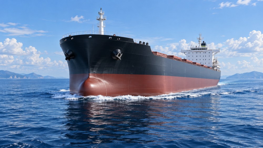
The bow is often the first hull area considered in low fuel consumption bulk carriers design because it strongly influences wave pattern and added resistance. Fuller bows support cargo capacity and structural efficiency, but they can generate larger bow waves if the entrance shape is not carefully developed. A finer entrance angle can reduce wave-making resistance around the intended operating speed, although excessive fineness may affect internal volume, steel weight distribution, slamming behavior, and practical cargo-hold geometry.
The better solution is rarely “make the bow as fine as possible.” Designers generally work to control how water is displaced and guided around the forebody. Waterline shape, flare, sectional-area distribution, shoulder geometry, and the transition toward the parallel mid-body all influence the result. A poorly resolved shoulder can produce separation or unfavorable pressure recovery, while an excessively full one can increase wave-making resistance.
For bulk carriers, bow flare is a particularly practical compromise. Some flare is needed to manage deck wetness and reserve buoyancy in head seas. Too much, however, can increase windage and contribute to slamming loads or added resistance in rough water. Computational fluid dynamics can identify trends early, but towing-tank validation and experience with comparable hull families remain valuable, especially where a proposed form pushes beyond established proportions.
Bulbous bows must match the real speed and draft
A bulbous bow can reduce resistance by modifying the bow-wave system, but it is not a universal fuel-saving attachment. Its effectiveness depends on hull form, vessel speed, loading draft, and the relationship between the bulb-generated wave and the wave system created by the main hull. A bulb designed around one narrow operating condition may deliver less benefit, or even impose a penalty, when the ship regularly slow-steams or sails in ballast.
This point has become more important as operating speeds have changed. A bulb suited to historical design speeds should not automatically be retained for a vessel expected to spend much of its life at lower speeds. Retrofit proposals need the same caution. Before changing a bow, evaluators should request comparative calculations or test evidence at representative drafts and speeds, including the ballast condition where feasible. A visually dramatic bulb is not proof of useful hydrodynamic performance.
Bow-height margin also deserves attention. A form that is efficient in calm-water calculations but performs poorly in waves may force speed reductions or create unacceptable slamming exposure. Fuel performance at sea is ultimately more valuable than a narrow calm-water result.
Stern lines and propeller inflow often decide the practical result
If the bow determines much of the ship’s resistance profile, the stern determines how efficiently engine power becomes thrust. The afterbody must guide water toward the propeller with as uniform and stable an inflow as practical. This is difficult on bulk carriers because their full hull forms, large propellers, shaft arrangements, and draft variation can create non-uniform wake fields.
Refined stern sections, appropriate buttock lines, and careful shaping around the propeller plane can improve wake distribution and reduce losses in the hull–propeller interaction. The target is not simply the lowest nominal wake fraction. An overly aggressive stern design may generate flow separation, cavitation risk, vibration, or steering difficulties. For an owner, a modest theoretical improvement is not attractive if it produces persistent noise, uncomfortable vibration, or repair exposure around the rudder and stern structure.
A large, slow-turning propeller is normally favorable for propulsive efficiency when draft and structural arrangements permit it. Hull design has to make room for that propeller: adequate immersion, a sensible aperture, acceptable clearance to the hull, and a clean flow path are all part of the same decision. Limiting propeller diameter to simplify aft-end geometry can shift the burden back to higher rotational speed and less favorable propulsive efficiency.
Appendages need to earn their complexity
Pre-swirl ducts, stator fins, rudder bulbs, twisted leading edges, and other energy-saving devices can improve the flow around a particular hull and propeller combination. Their value is highly configuration-dependent. A device that performs well on one series of ships may not transfer cleanly to another vessel with different block coefficient, propeller loading, rudder profile, or operating draft.
The evaluation should go beyond a predicted percentage saving. Teams should examine structural attachment details, corrosion protection, debris exposure, dry-docking access, coating repair procedures, and whether the device complicates inspections. In ports with floating debris, ice exposure, or frequent shallow-water operation, a protruding appendage has a different risk profile than it does on a deep-sea route. The hydrodynamic gain must survive the operating environment.
Frictional resistance: the coating issue is a hull-design issue in service
A well-designed hull can gradually lose its advantage if the underwater surface condition is neglected. Frictional resistance is directly affected by roughness, fouling, coating degradation, weld seams, damage repairs, and marine growth around sea chests, bilge keels, rudder surfaces, and propeller areas. This is not a minor maintenance topic; it is a central part of operational fuel use.
Hull coatings should be selected for the anticipated idle time, water temperature, trading regions, cleaning access, and docking schedule. A coating strategy that is acceptable for a vessel in continuous deep-sea service may not perform the same way for a ship spending extended periods at anchorage. The technical specification should also define how coating condition will be monitored and what repair quality is expected after damage. Poorly faired local repairs can introduce roughness precisely where flow is sensitive.
Propeller condition belongs in this conversation. Surface damage, biofouling, and roughness affect efficiency even when the hull itself remains reasonably clean. A practical performance-management program tracks both hull and propeller condition instead of attributing every fuel deviation to weather or engine behavior.
Trim tolerance is more useful than a single “best trim”
Bulk carrier crews often use trim as an operational lever, but hull design determines how much benefit can realistically be extracted. The vessel may show a preferred trim in model testing or digital simulations, yet cargo distribution, ballast-water constraints, port limitations, sloshing considerations, visibility rules, and structural limits can restrict its use. A design that remains efficient across a practical trim range is often more valuable than one with a sharp optimum that is difficult to maintain.
This is why technical evaluators should check whether the performance prediction includes relevant trim cases. The question is not just “what trim gives the lowest power?” It is “how sensitive is the vessel to trim, and can the crew achieve that condition safely and consistently?” For a ship that alternates between cargo grades or loading ports, this distinction can materially affect annual fuel demand.
How to review a bulk carrier hull without relying on marketing claims
A disciplined review normally combines hull-form drawings, hydrostatic data, resistance and propulsion predictions, model-test documentation where available, propeller and cavitation information, and a clear statement of assumptions. Sea margin, hull roughness allowance, wind assumptions, and loading condition must be visible. If they are not visible, comparisons between designs can be misleading.
It is also sensible to separate baseline hull efficiency from claimed savings delivered by add-on devices or operating practices. The distinction matters when estimating compliance-ready performance under IMO efficiency requirements, planning engine power reserves, or comparing alternative fuels. A hull form remains in service for decades; machinery, software, and some appendages can be upgraded later. That makes early hull-form discipline unusually consequential.
MO-Core’s wider work on deep-blue manufacturing, electric propulsion, LNG systems, and marine emissions technology reinforces a useful principle: efficiency is rarely created by one component. On a bulk carrier, the hull, propeller, engine operating point, coating condition, and voyage profile must agree. Advanced propulsion controls can reduce avoidable losses, but they cannot fully compensate for a hull whose bow or stern was optimized for the wrong operating reality.
The practical design priority
The hull features most likely to reduce fuel use are an appropriately shaped forebody, a bulbous bow matched to real speed and draft, a stern that delivers clean propeller inflow, carefully integrated appendages, and an underwater surface that can remain smooth in operation. None should be judged in isolation.
For a technical evaluator, the most reliable indicator is not a headline fuel-saving claim. It is a transparent performance package showing how the vessel behaves in laden and ballast conditions, at the speeds it is expected to sail, with workable trim and maintainable hull details. That is where efficient bulk carrier design moves from an attractive concept to an operationally credible ship.