
Related News
- 00
0000-00
Energy-Efficient Ship Design: Matching Hull and Propeller to Service Speed - 00
0000-00
Modeling Cryogenic Tank Sloshing: When Does Phase Change Matter in CFD? - 00
0000-00
Choosing Heavy-Lift Crane Vessels for Offshore Projects: Capacity and Outreach - 00
0000-00
Choosing a Ship Component Availability Database: Stock Accuracy and Lead Times - 00
0000-00
How Low-Carbon Navigation Systems Optimize Ship Routes to Reduce Fuel Use

How Do VFDs Affect Onboard Power Quality?
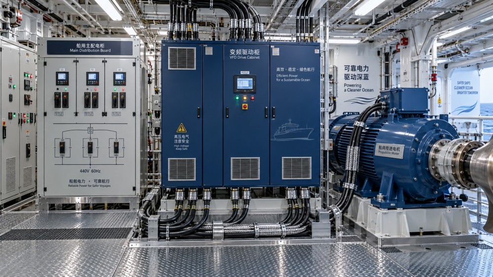
Variable frequency drives have become routine equipment on modern vessels. They control propulsion motors, thrusters, seawater pumps, HVAC fans, cargo compressors, cranes, winches, refrigeration machinery, and a growing number of hotel-service loads. Their operating advantages are obvious: motors run closer to the speed actually required, mechanical throttling losses fall, and automated control becomes more precise.
But the answer to how do VFD drives affect onboard power quality? is not simply “they create harmonics.” A VFD changes the electrical character of the ship’s network. On a land-based plant, a utility grid may absorb part of that disturbance. Onboard, the generating plant, switchboards, transformers, cable runs, sensitive electronics, and large nonlinear loads all sit inside a comparatively compact electrical island. That makes design choices, operating modes, and load combinations much more consequential.
For electric-propulsion ships, LNG carriers, offshore construction vessels, and large cruise vessels, the question is especially practical. A drive system may improve fuel efficiency while simultaneously making voltage waveform control, generator loading, protection coordination, and electromagnetic compatibility harder to manage. Good integration captures the efficiency benefit. Poor integration can turn a well-specified drive into a recurring source of nuisance trips and difficult fault-finding.
Why a VFD changes the shipboard electrical environment
Most conventional VFDs rectify incoming AC power into DC and then invert it into variable-frequency AC for the motor. That conversion process draws current in pulses rather than as a smooth sinusoidal waveform. The result is harmonic current, which interacts with the impedance of generators, transformers, cables, and other connected equipment.
The drive does not necessarily create a serious power-quality issue on its own. Problems arise when the aggregate harmonic current is large relative to the available generation capacity, when the electrical network has resonance points, or when operational conditions change faster than the power-management strategy expects. A vessel can look acceptable during harbor tests and behave very differently when several propulsion drives, cargo machines, chilled-water pumps, and accommodation loads are running together.
Marine networks are particularly sensitive because generator capacity is finite and network configurations are often reconfigured. A bus-tie may be open during one operating mode and closed in another. One generator may be online in port, while multiple sets support maneuvering or dynamic positioning. The same VFD fleet therefore sees different source impedances over the vessel’s operating profile. Harmonic performance has to be assessed across those states, not at one nominal point.
The main power-quality effects engineers watch
The most visible effect is voltage distortion. Harmonic currents flowing through the network impedance distort the voltage available to other loads. Distortion can affect equipment that was never intended to share a bus with large converter-fed motors: navigation electronics, automation controllers, communication equipment, UPS systems, lighting drivers, instrumentation, and protection relays all deserve attention.
A second concern is generator heating and unstable loading. Harmonic currents add losses in alternators and transformers. Depending on the machine design and operating condition, this may reduce the practical margin available for a generator set. The operational consequence is not always a dramatic blackout. More often, it appears as unexpectedly high temperature, poor power factor behavior, an inability to load a generator as anticipated, or alarms that only occur in specific drive-speed ranges.
Then there is electromagnetic interference, commonly shortened to EMI. The inverter output switches rapidly, producing steep voltage edges. These can couple into nearby signal cables, control circuits, shaft monitoring systems, or communication wiring if cable segregation, shielding, earthing, and termination practices are weak. A crew may describe the symptom as “intermittent automation noise,” yet the root cause may be a cable-routing decision made long before commissioning.
Common-mode voltage and bearing-current risk also deserve a place in the discussion. Fast-switching drive outputs can induce currents through motor bearings and shaft paths. On high-duty equipment, this can contribute to premature bearing damage unless the motor, grounding arrangement, insulation system, and any shaft-earthing or bearing-protection measures are considered as one package.
Not every vessel experiences the same problem
A small pump VFD on an auxiliary system and a multi-megawatt propulsion converter do not place the same demands on the network. The risk also changes with vessel type.
On a luxury cruise vessel, the challenge is often diversity and sensitivity. There may be extensive hotel loads, large HVAC plants, galley systems, entertainment equipment, redundant power paths, and passenger-facing systems that cannot tolerate unexplained interruptions. Even a disturbance that does not threaten propulsion can generate a service problem if it affects lighting controls or onboard IT systems.
On an LNG carrier, electrical continuity sits alongside cryogenic cargo-handling priorities. Cargo compressors, pumps, and auxiliary systems may involve significant motor loads, while operational redundancy and hazardous-area considerations complicate every retrofit or modification. Here, it is not enough to ask whether a filter reduces harmonics. Engineers need to understand whether it introduces losses, heat, maintenance requirements, space constraints, or an unwanted interaction with the wider power-management philosophy.
For offshore engineering vessels and DP-capable ships, transient behavior can become the deciding factor. Thrusters, cranes, pumps, and mission equipment may change load quickly. Drive controls, generator governors, excitation systems, and power-management functions must respond as a coordinated system. Harmonics are one part of the electrical picture; rapid load steps, bus stability, redundancy cases, and fault recovery matter just as much.
Harmonics are not the only reason a drive installation misbehaves
It is easy to blame “harmonics” whenever a ship has electrical trouble after a VFD upgrade. That diagnosis is often incomplete. A drive may expose an existing weakness in generator control, transformer sizing, earthing continuity, cable installation, or protection settings. In other cases, a filter installed to solve one issue can create resonance at a particular frequency if the system study did not account for actual network impedance.
Capacitor banks deserve particular caution. They can be useful in certain electrical arrangements, but adding capacitance to improve power factor without studying harmonic interaction is risky. In a converter-rich system, capacitance and inductance can form resonant circuits that amplify rather than suppress a troublesome frequency component. The vessel may then experience abnormal currents, capacitor stress, fuse operation, or voltage distortion that appears only in a narrow operating window.
Another common oversight is treating the input side and motor side of the VFD as the same problem. Input harmonics influence the ship’s AC network. Output switching stresses the motor cable, insulation, bearings, and nearby control circuits. A line reactor or active front end may address one side of the equation, while a sine-wave filter, dV/dt filter, cable-length review, or motor specification may be needed on the other.
What mitigation looks like in real design work
The best mitigation is selected before equipment is purchased. That starts with a network study based on realistic operating modes: harbor operation, sea passage, maneuvering, cargo transfer, DP operation where applicable, generator-out cases, and black-start or recovery arrangements. It should include expected nonlinear load combinations, not only the largest single drive.
Several approaches are commonly considered, although none is automatically right for every vessel:
- Input line reactors or DC chokes can reduce current distortion and limit inrush-related stress in many standard drive arrangements.
- Passive harmonic filters may be effective where the load profile and network impedance are sufficiently well understood, but they require careful resonance assessment.
- Active harmonic filters can offer flexibility when harmonic content varies substantially with operating mode, though their own rating, redundancy, control integration, and maintenance implications must be reviewed.
- Multi-pulse rectifier arrangements have historically been used to reduce characteristic harmonics, usually with transformer and space implications.
- Active front-end drives can provide low-distortion input current and bidirectional power flow, but they are not a universal shortcut. Their control behavior, EMC design, fault response, and interaction with the ship’s source must be engineered properly.
Physical installation is just as important as the topology. Keep power and low-level signal cables properly separated. Follow manufacturer requirements for shield termination rather than treating shielding as a generic add-on. Check bonding and grounding paths at cabinets, motors, transformers, and switchboards. Verify cable lengths against the drive and motor limits. In practice, many post-delivery problems are installation details rather than a fundamental defect in the drive technology.
How should compliance and acceptance be approached?
There is no sensible single number that defines “good” onboard power quality for every ship. Project requirements may be shaped by flag-state expectations, classification-society rules, equipment manufacturers’ limits, and applicable marine electrical standards. IEC 60092 is widely relevant to shipboard electrical installations, while harmonic guidance may also be referenced through project specifications or broader electrical standards. The applicable limits and measurement locations need to be confirmed for the vessel rather than copied from a shore-based industrial project.
Acceptance should combine analysis and measurement. A harmonic study is a design tool, not a substitute for commissioning tests. During harbor acceptance and sea trials, the team should capture voltage and current waveform data under meaningful load states. That includes low generator-count operation, major VFD combinations, transition events, and any condition known to be sensitive. Measurements without a record of generator configuration and load status are far less useful when diagnosing a later issue.
The practical question is whether the system remains stable, equipment stays within its intended limits, and critical functions continue to operate through realistic operating changes. A clean-looking waveform at one switchboard does not prove that a remote motor, UPS input, or control cabinet sees an acceptable environment.
A decision point for retrofit projects
Retrofitting VFDs onto pumps and fans can produce worthwhile operational savings, especially where flow is routinely controlled by throttling valves or dampers. Yet retrofit teams should resist the assumption that smaller drives are electrically insignificant. Multiple modest drives added over several drydock cycles can materially change the nonlinear-load profile of an aging shipboard network.
Before approving a retrofit, review available single-line diagrams, generator data, transformer information, protective-device settings, existing power-quality records, cable routes, and the intended operating pattern. If those documents are incomplete, field verification may be more valuable than an elaborate theoretical model built on uncertain inputs. This is a familiar lesson across high-value marine systems: the reliability of the engineering conclusion cannot exceed the reliability of the vessel data behind it.
The balanced view: VFDs are part of the solution
VFDs are central to modern marine electrification. They support efficient electric propulsion, finer thruster control, better pump and compressor regulation, and operating strategies that can reduce unnecessary fuel use. Those benefits align naturally with the industry’s broader push toward lower-emission operation, whether the vessel uses conventional fuel, dual-fuel machinery, batteries, fuel cells, or a hybrid architecture.
For the deep-blue sectors tracked by MO-Core—from complex engineering vessels to cruise systems and LNG transport—the real engineering task is integration. A VFD should be evaluated as part of a living electrical ecosystem, not as a standalone efficiency device. When harmonic performance, EMC, generator behavior, cable design, protection, and operating modes are addressed together, onboard power quality becomes manageable rather than mysterious.
If a vessel already shows unexplained trips, overheating, control interference, or unstable generator loading, start with measured evidence and the actual operating configuration. Replacing components before identifying the interaction usually costs more than it saves.